Build and run Windows Failover Clusters on VMware ESXi
Yes, you read the title right. We ca run Microsoft Windows Failover Clusters on VMware ESXi hosts, and believe it or not, a lot of companies are doing it nowadays. It’s cheap, and it does the job very well. All we need is at least one ESXi host and two Windows Server VMs that will run as nodes in the Failover Cluster and we are done; no more extra switches, no more buying extra network adapters and especially no more complicated configurations.
Now, as a bonus, VMware has made this possible in three “flavors”, and here they are:
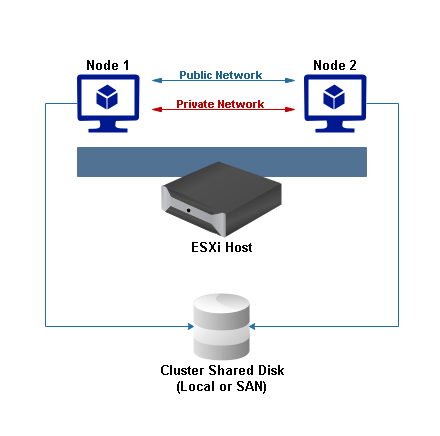
Cluster in a Box (CiB) – Is the configuration where the VMs participating in a Failover Cluster are running on the same ESXi host. This is the easiest of the three configurations to set up, but it’s also the one that does not protect you against a hardware failure. As you will see later in the article, the VMs participating in the Failover Cluster cannot be spread across ESXi hosts, and with this, they are not recommended for production environments that need a high uptime since they do not benefit of the HA feature of vCenter. VMDK files are recommended for the shared disks on this type of cluster.
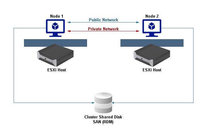
Cluster across Boxes (CAB) – With this type of configuration, the VMs are running on different ESXi hosts, which means that VMs participating in the cluster are protected against a single host failure. Even tough this is good news, vMotion and vSphere Distributed Resource Scheduler (DRS) are still not supported (at the time of this writing) for Microsoft-clustered VMs.
UPDATE: Starting with VMware vSphere 7.0, VMDKs can now be used as a shared (clustered) resource. A VMDK can be used as a shared disk resource for a WSFC deployed on VMs hosted on different ESXi hosts. Using a ESXi hosts with a version lower then 7.0 can cause slow boot times and become unresponsive. A host with a version lower than ESXi 7.0 cannot mount a clustered VMDK datastore. This is because the ESXi hosts on which WSFC VMs run must have physical SCSI-3 WEAR type reservation on the LUN. For more details please check this document and the guide.
Taken from Recommendations for using Clustered VMDKs with WSFC
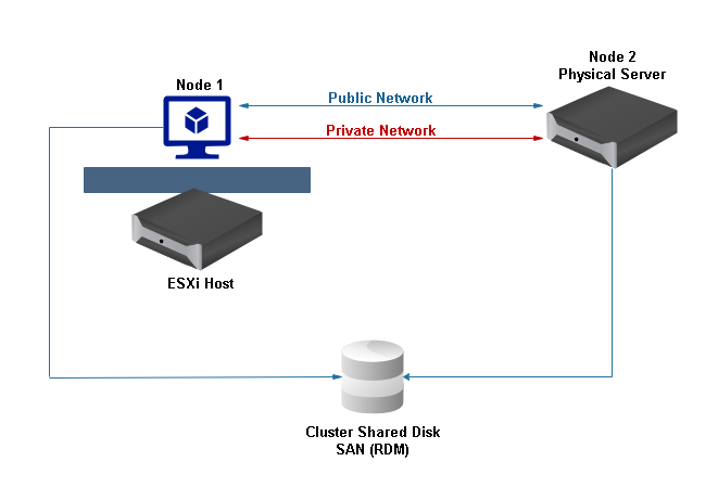
Physical-to-Virtual – This is the type of configuration where at least one physical server and at least one VM are joined together in a Failover Cluster. Having this setup, gives us the best of both worlds; the only restriction is that you cannot use Virtual Compatibility mode with the RDMs.
Before jumping into the configuration part, I think it’s important to list the setup requirements and limitations in order for the deployment to work and get VMware support when needed.
| Component | Requirement |
| Virtual SCSI adapter | LSI Logic Parallel for Windows Server 2003. LSI Logic SAS for Windows Server 2008 SP2 and above. VMware Paravirtual for Windows Server 2008 SP2 and above. |
| Operating system | Windows Server 2003 SP1 and SP2, Windows Server 2008 SP2 above releases. |
| I/O timeout | Modify the Windows registry disk timeout value to 60 seconds or more. Modify HKEY_LOCAL_MACHINESystemCurrentControlSetServicesDiskTimeOutValue. |
| Disk format | Thick Provision in eagerzeroedthick format. |
| Number of nodes | Windows Server 2003 SP1 and SP2 : two-node clustering Windows Server 2008 SP2 and above: up to five-node clustering |
| NTP server | Synchronize cluster nodes time with a common NTP server (domain controller), and disable host-based time synchronization when using clustering in the guest. |
And for the disks type, we have to use the ones in the following table:
| Storage Type | Clusters on a single ESXi host Cluster in a Box (CiB) |
Clusters across ESXi hosts Cluster across boxes (CAB) |
Clusters of Physical and Virtual Machines (Standby Host Clustering) |
| Virtual Disks (VMDK’s) | Yes (recommended) | No | No |
| Pass-through RDM (physical compatibility mode) | No | Yes (recommended) | Yes |
| Non-pass-through RDM (virtual compatibility mode) | Yes | No | No |
1. Cluster in a box (CIB)
1.1 Configuring the SCSI controller for the Windows Virtual Machines
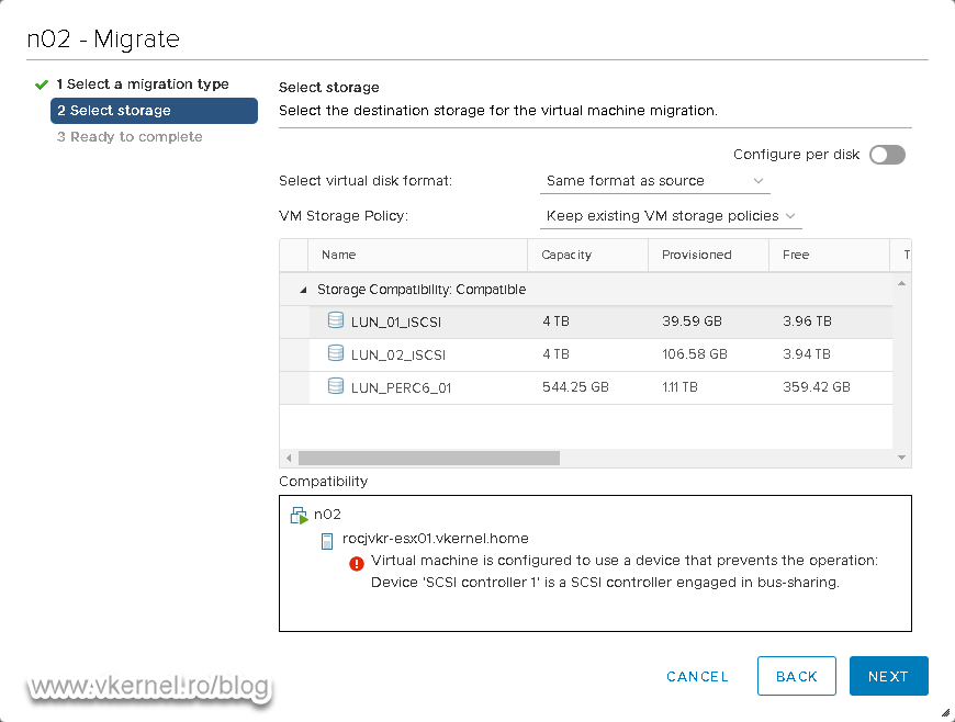
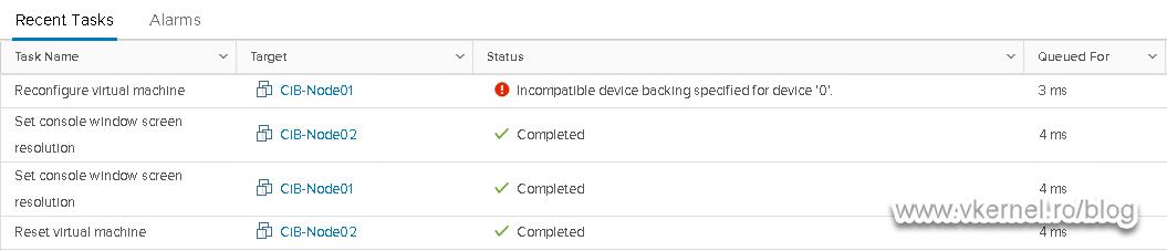
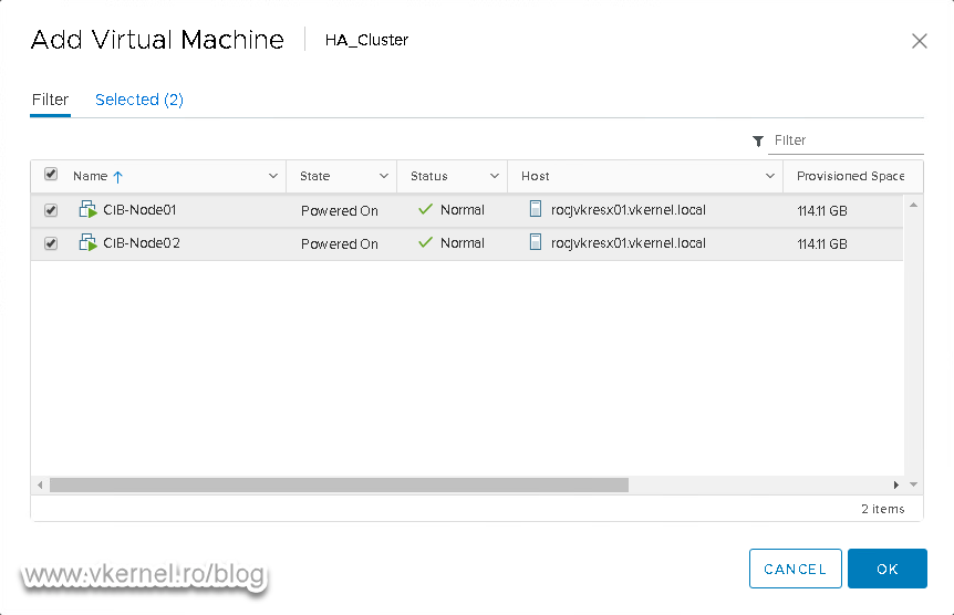
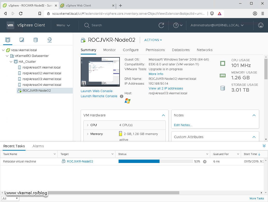
As mention in the beginning of the article, this is the simplest cluster option of all three but also the less safer one. All we need is at least two VMs, one ESXi host, and a datastore. The configuration of the Windows VMs/nodes needs to be from the start on a single ESXi host and not spread around in your VMware cluster, or you will get the bellow error message when you try to put all the Windows VMs back on this one ESXi server. If you do not have a VMware cluster, ignore this and move forward with the configuration.
Virtual machine is configured to use a device that prevents the operation: Device ‘SCSI controller 1’ is a SCSI controller engaged in bus-sharing.
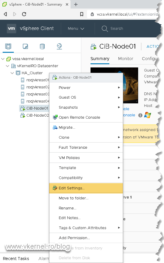
Thinking that you already deployed the number of VMs you want to put in the Windows Failover Cluster, right-click one of them and choose Edit Settings.
Once the virtual machine Edit Settings window opens, click the Add New Device button then choose SCSI Controller. Now expand the New SCSI controller configuration and from the SCSI Bus Sharing drop-down-box choose Virtual. We need to add this new controller with this new configuration in order for the VMs to be able to share the same disk(s).
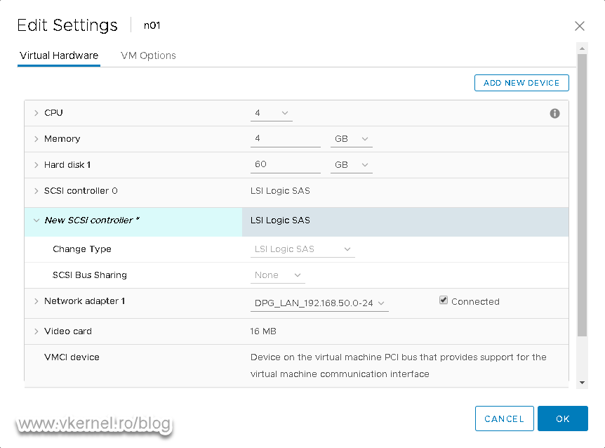
Repeat the operation for the other VMs that you want them to participate in your Windows Failover Cluster.

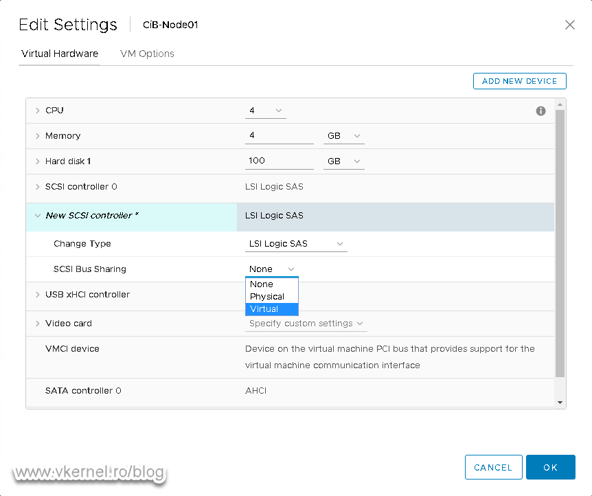
Just a mention here! If your ESXi server is not running in a VMware cluster environment, configuring the SCSI controller Bus Sharing while the VMs are running will not work, the option is disabled. You will have to shut down the VMs in order to configure the new SCSI controller.
1.2 Creating the cluster virtual disk(s) for the Windows Virtual Machines
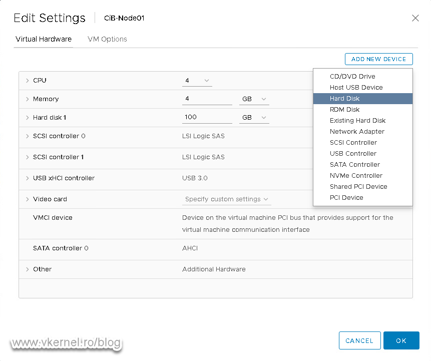
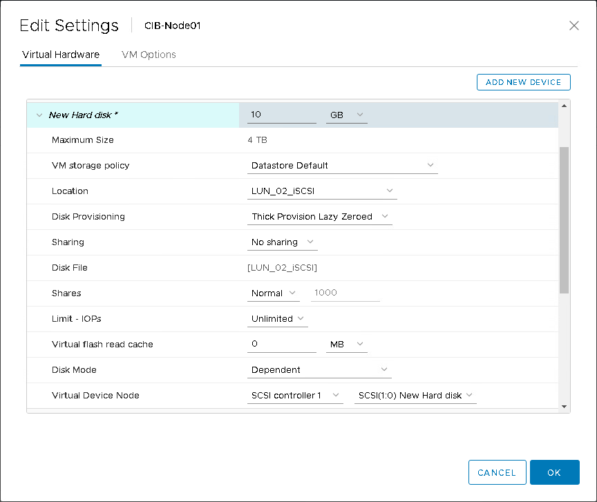
Now open again the Settings for one of the VMs, click the Add New Device button and choose Hard Disk.
Type a size for the new disk. This is going to be one of the Windows Failover Cluster disk resources, so make sure you create it with the right size to accommodate your data.
From the Location option we can choose to place the new virtual disk on a different datastore, or keep it within the virtual machine’s folder. This is not a must and it works either way.
From the Disk Provisioning option choose Thick Provision Eager Zeroed. I know many of you don’t want to use it because it provisions the entire disk size, taking datastore space, but this is the only option that works and is supported by VMware for a CiB deployment. If you try to use any of the other two disk provisioning options you will get the bellow error message later on when configuring the rest of the Windows VMs, and the adding of the virtual disk will fail.
Incompatible device backing specified for device ‘0’.
The last setting that we need to configure here is the Virtual Device Node one. From the drop-down-box choose the controller we added a few moments ago (section 1.1), SCSI controller 1 in my case. This is a must, because as you remember, this controller offers us the possibility to share the virtual disk(s) between multiple VMs. Click OK when you’re done.
Based on VMware’s documentation, the multi-writer feature must not be used for a clustered disk resource for WSFC, so set to No sharing on the Sharing drop-down box.
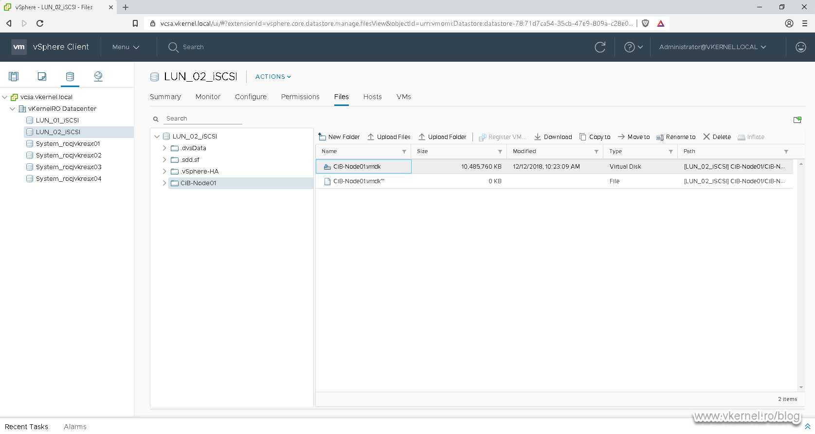
Depending on the size of the virtual disk you set up, the operation can take quite some time. I configured mine on a different LUN, a LUN that I know it’s fast, and by browsing the datastore we can see the virtual disk in its full size.
Feel free to create other virtual disks that you think you need in the Windows Failover Cluster using the above steps. The only thing that will be different is the SCSI ID number, which increase as you add new virtual disks. Here, for the second disk that I added to use for my quorum drive, the controller is still the same, but the ID has changed to 1:1 since 1:0 was already taken.

1.3 Adding cluster virtual disk(s) for the rest of the Windows Virtual Machines
We are now done with the configuration of the first VM, so let’s move on to the other one(s) with the taught in mind that you already have added the second SCSI controller as discussed in section 1.1.
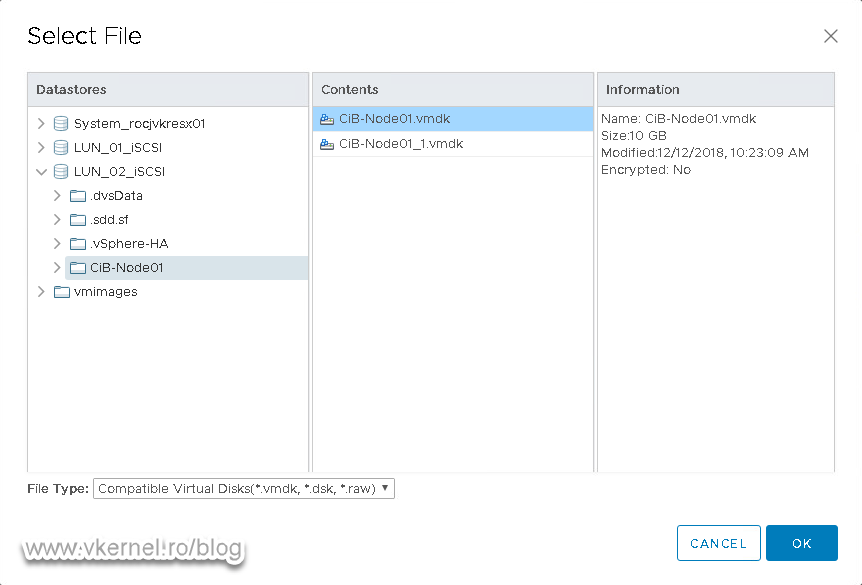
Open the settings for the second machine, click the Add New Device button and choose Existing Hard Disk.
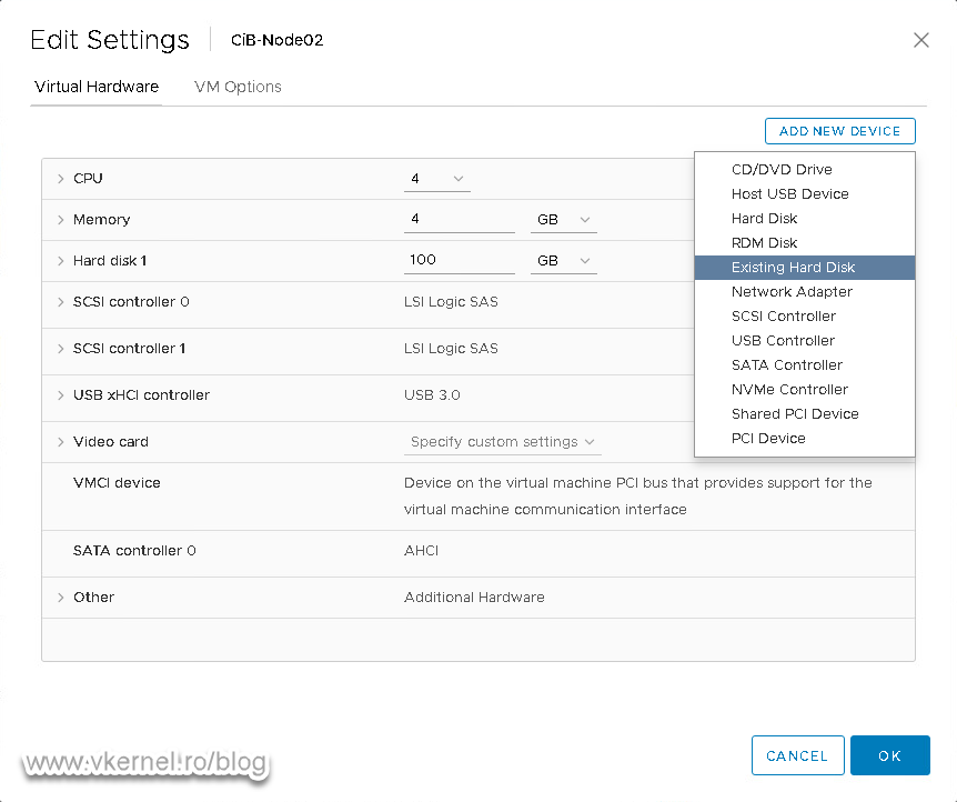
From the datastore browser window that opens, select the disk(s) we created on the first VM then click OK.
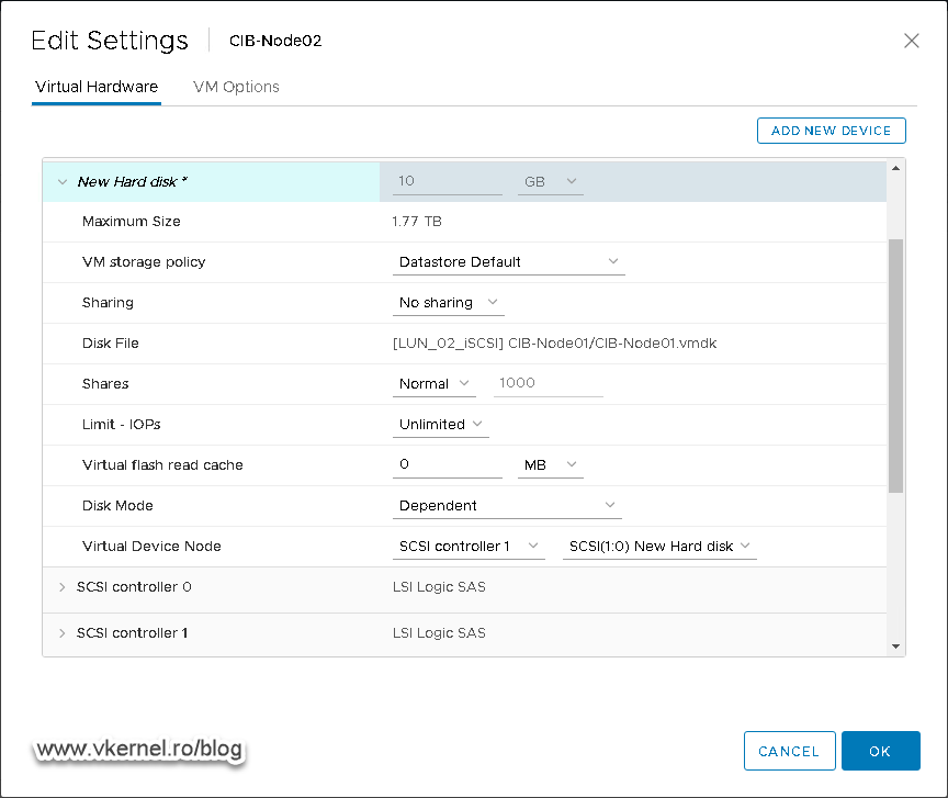
We need to configure the disk(s) to be identical with the one(s) from the first VM. Set the the Virtual Device Node to SCSI controller 1 on ID 1:0. Off course, the next virtual disk that you add will be on SCSI ID 1:1, the third one on SCSI ID 1:2, and so on, but they need to be the same as the first VM that you configured.
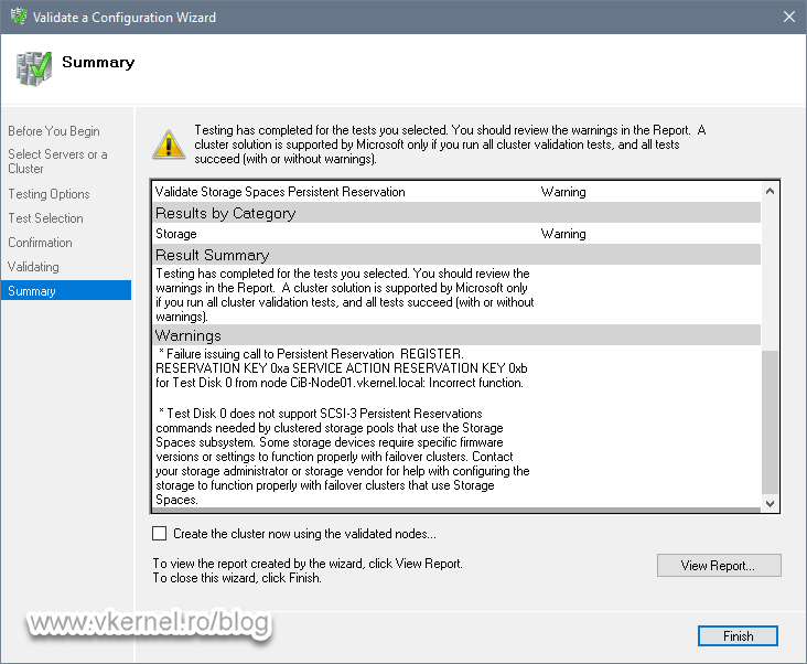
Once you’re done with this, go ahead and build the Windows Failover Cluster. During the Validate a Configuration Wizard you might get a warning about the SCSI 3 persistent reservation. This is because your storage is not configured or does not support SCSI 3 persistent reservation. The only way to get rid of the warning is to re-configure your storage with the mentioned feature.
Test Disk 0 does not support SCSI-3 Persistent Reservations commands needed by clustered storage pools that use the Storage Spaces subsystem. Some storage devices require specific firmware versions or settings to function properly with failover clusters. Contact your storage administrator or storage vendor for help with configuring the storage to function properly with failover clusters that use Storage Spaces.
1.4 Creating VMware affinity rule for the clustered Windows Virtual Machines
We are almost done. The only thing left is to create an affinity rule so our VMs participating in the Windows Failover Cluster will be kept together, on the same ESXi host -for those that have a VMware Cluster-.
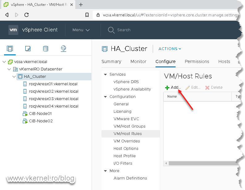
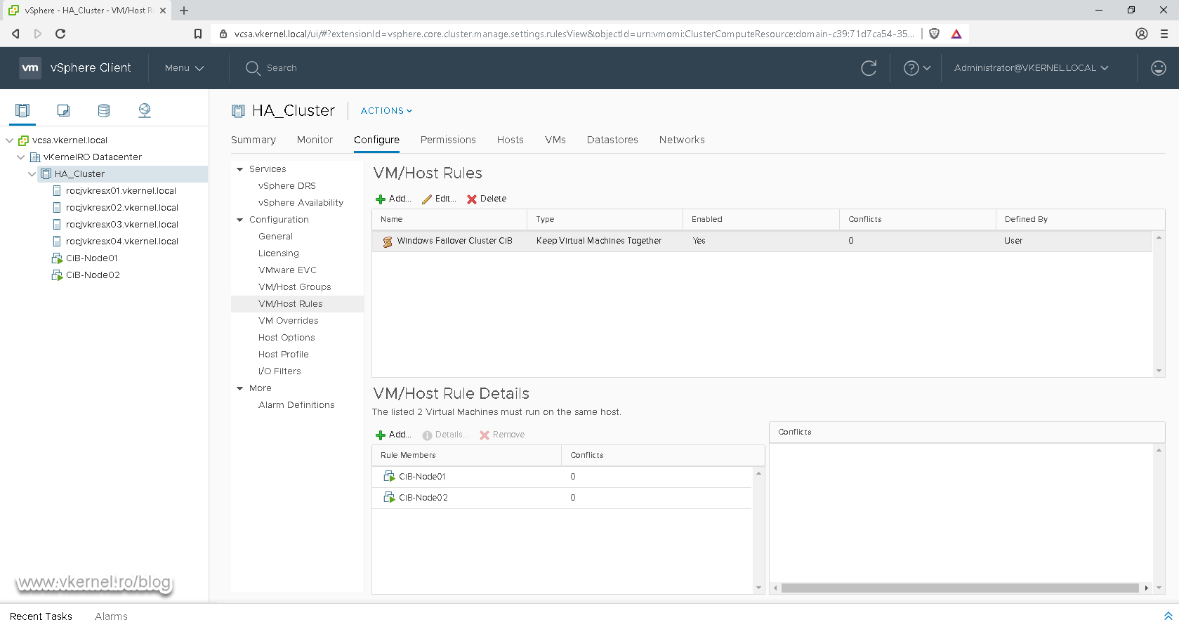
Go to Configure > Configuration > VM/Host Rules. Here, push the Add button.
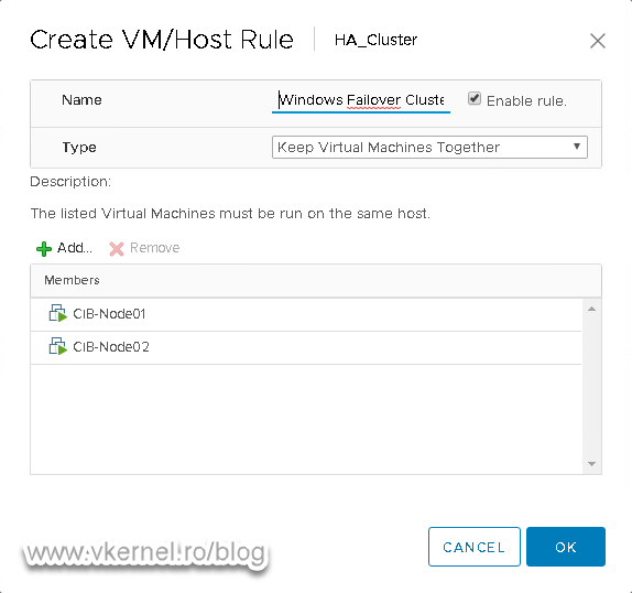
Give the rule a name then select Keep Virtual Machines Together from the Type drop-down box. Now we have to chose what VMs do we want to keep together/on the same host. For that, click the Add button and select the Windows nodes/VMs participating in the Windows Failover Cluster. Once you’re done, click OK twice.
And here we have our affinity rule that keeps our Windows VMs together.
Based on VMware’s documentation we also need to configure an advanced setting on DRS so the affinity rule is strictly applied.
Select your VMware cluster and go to Configure > Services > vSphere DRS. From the Actions pane click the Edit button.
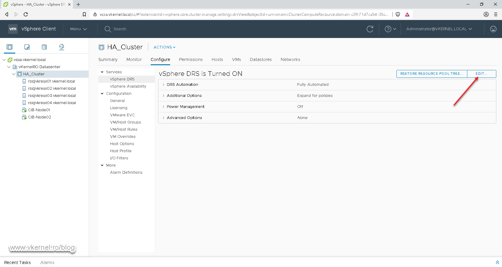
The Edit Cluster Settings window opens. From the Advanced Options tab, click Add.
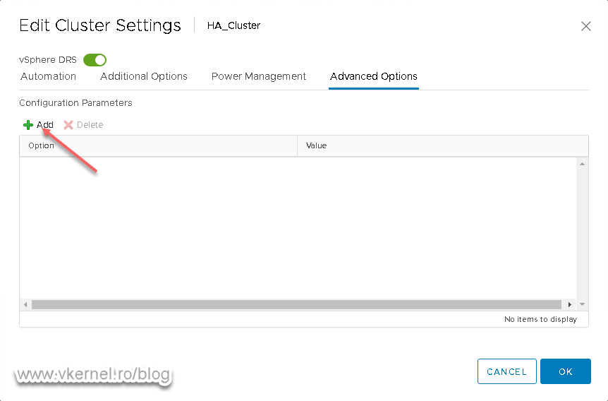
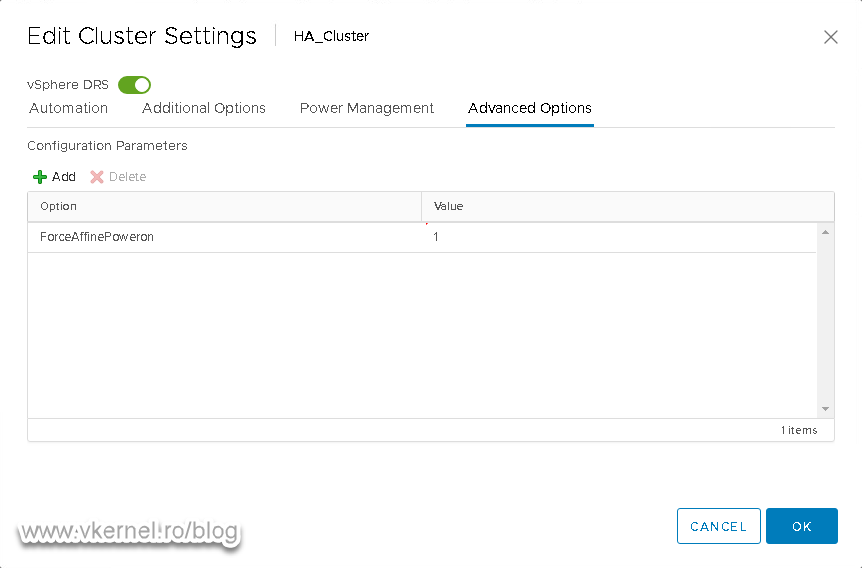
In the Options column type ForceAffinePoweron, then in the Value one type 1. Click OK to save the changes.
We now have our CiB configured and ready. Off course, there is still the Windows Failover Cluster configuration part, but I will leave that up to you. Just let me know how it goes in the comments area of the article.
2. Cluster across Boxes (CAB)
2.1 Configuring the SCSI controller for the Windows Virtual Machines
This second type of cluster is the most popular for business critical applications because it allows us to put the Windows nodes on different ESXi hosts and take advantage of vCenter HA and vMotion. The configuration is pretty much the same as CiB, the only difference are the disks. We don’t have virtual disks anymore (VMDKs), we have RAW disks or RDMs. This means that we are going to map our LUNs from our storage device directly to the Windows VMs/nodes.
As mentioned in the begging of the article, starting with vSphere 7.0 we can use VMDKs as a clustered resource.
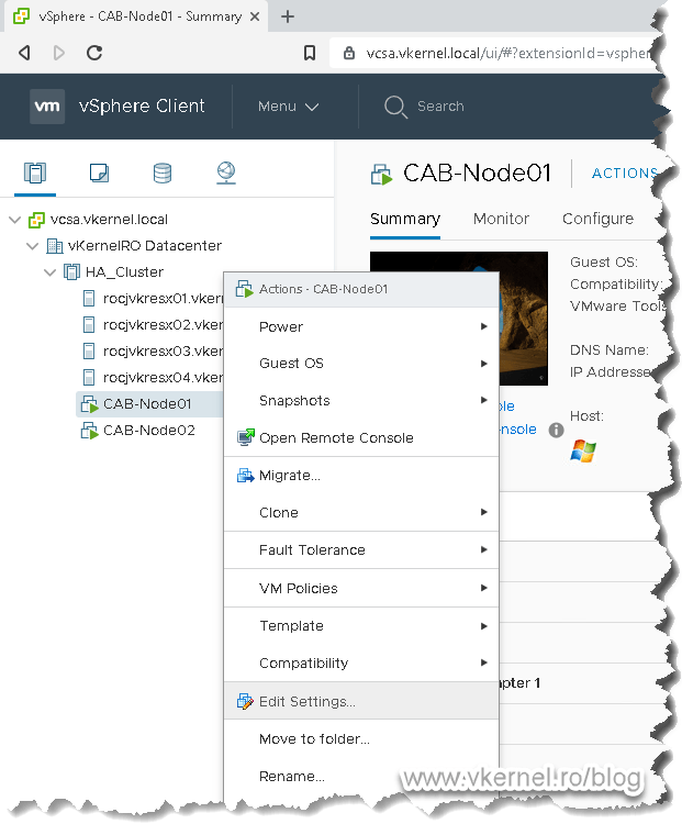
Go ahead, prepare your LUNs on you storage array but do not add them as datastores in vCenter, just leave them there un-formatted and untouched. Now right-click the first Windows VM and choose Settings.
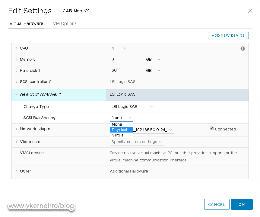
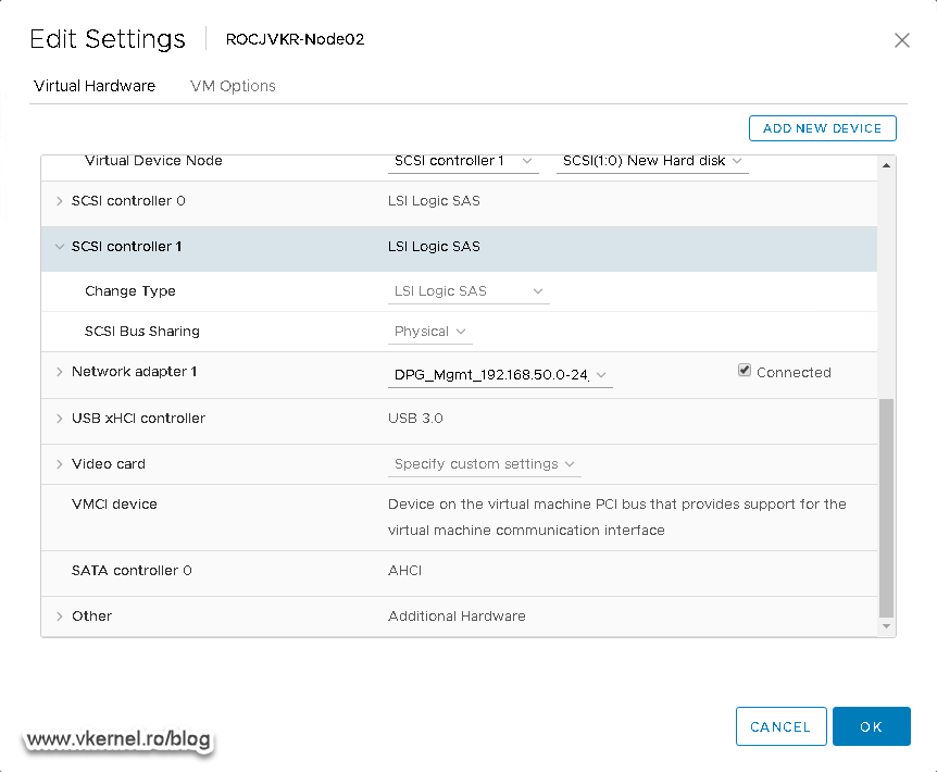
Once the Edit Settings window opens, add a new SCSI controller, but this time set the SCSI Bus Sharing to Physical. This is a must in order for the VMs to be able to sit on different ESXi hosts and share the same SCSI bus. Click OK when you are done.
Repeat the same operation for the rest of the VMs that participate in the Windows Failover Cluster.
2.2 Adding RDM (RAW) disks to the Windows Virtual Machines
Now let’s add the LUNs to our VMs. Open the Edit Settings window again on the first VM and add a new RDM Disk.
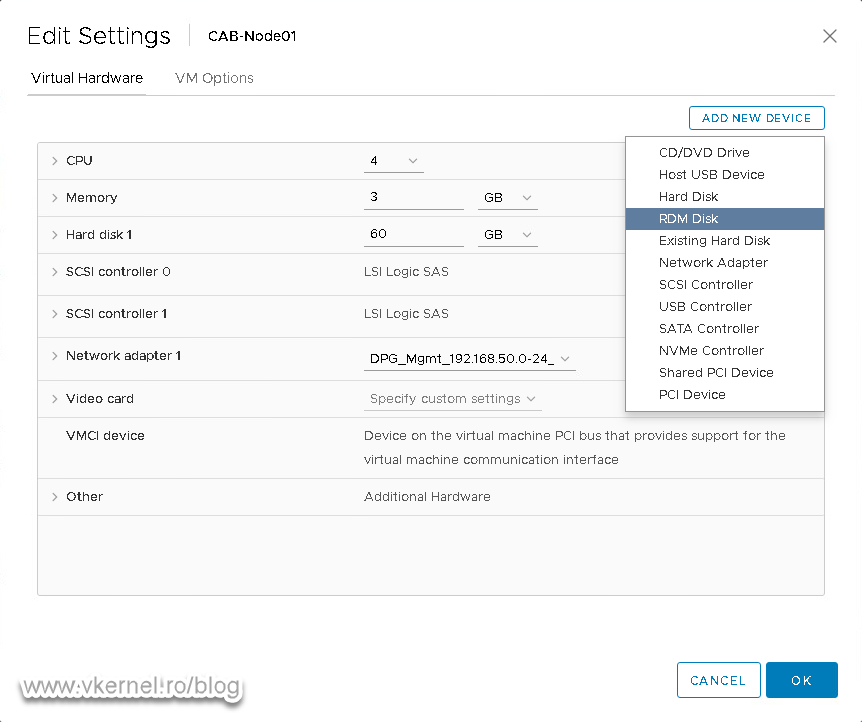
On the Select Target LUN window that pops-up, select one of your LUN(s) then click OK.

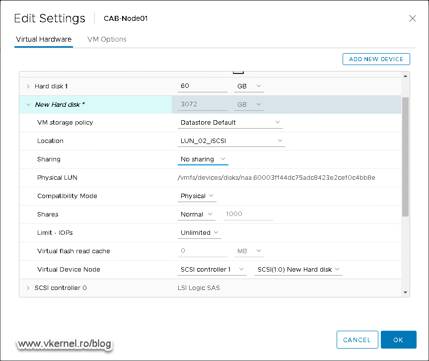
As in the CiB section, we have some settings to configure on the disk before we can actually use it.
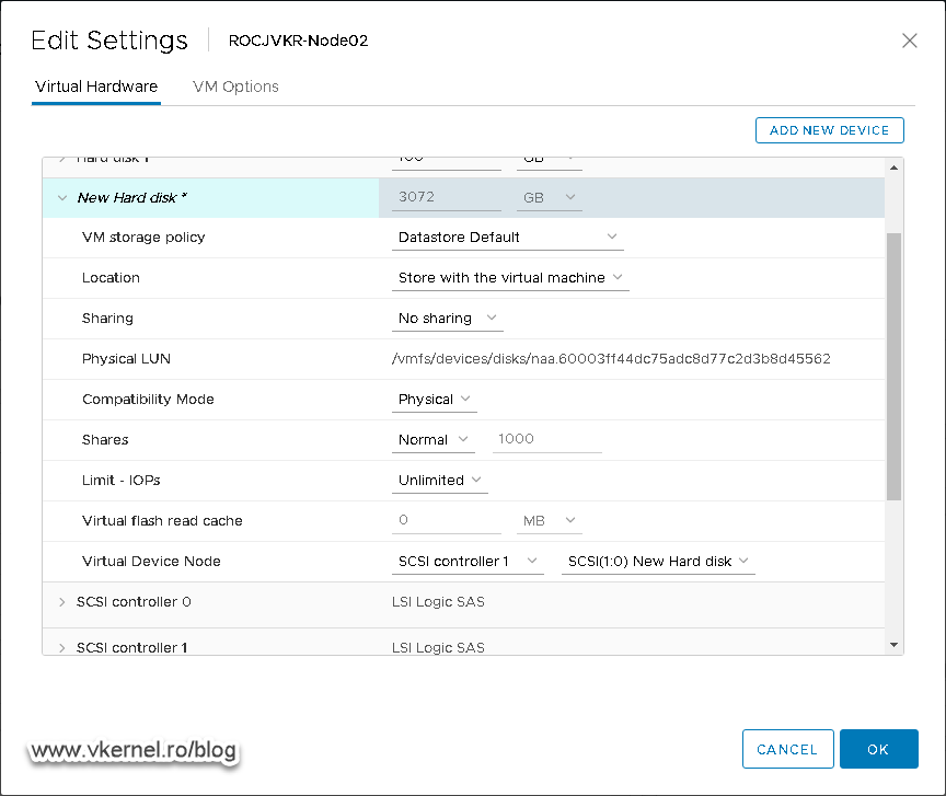
On the Location drop-down box we can change the location of the virtual file. Yes, even if we use RDM disks, we still have a virtual file created, which is actually a pointer to the RAW disk. You can read more about it here. As before, set the Sharing option to No sharing and make sure the Compatibility Mode is set to Physical. On the Virtual Device Node, choose the second SCSI controller, the one we added just a moment ago then click OK.
Based on VMware’s documentation, the multi-writer feature must not be used for a clustered disk resource for WSFC, so set to No sharing on the Sharing drop-down box.
Repeat this operation for the rest of the RDM disks you need to add to this VM.
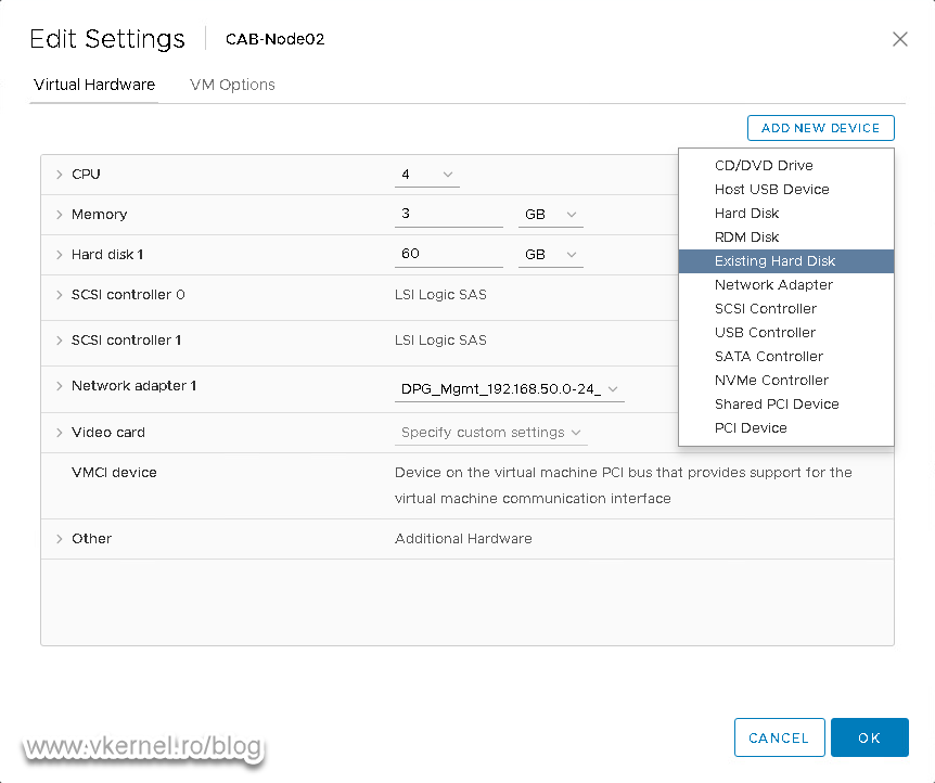
On the second VM, or the rest of them -if you are building a Windows Failover Cluster with more than two nodes- add an existing hard disk.
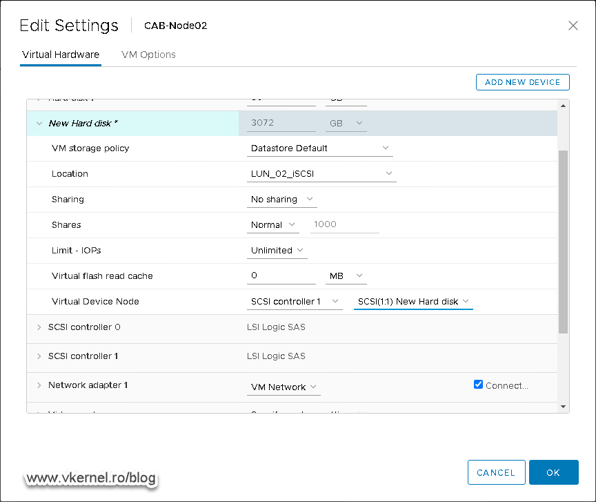
Choose the virtual file/pointer that was created with the first VM and set the Sharing option to No sharing mode. From the Virtual Device Node option, set the controller to SCSI controller 1 with the same SCSI ID as the first VM.
Click OK when you are done then add the rest of the disks you might have. Off course, repeat this operation for the rest of the VMs.

2.3 Creating VMware anti-affinity rule for the clustered Windows Virtual Machines
In the CiB section, we created an affinity rule to keep the VMs together. Now we have to create an anti-affinity rule to keep the VMs apart from each other so in case one of the ESXi hosts fails, we still have at least one VM/node running and not making the Windows Failover Cluster unavailable.
Once again, click your VMware cluster name and go to Configure > Configuration > VM/Host Rules. From the Actions pane, hit the Add button.

Name the rule, add your Windows VMs into the list, then from the Type drop-down box choose Separate Virtual Machines.
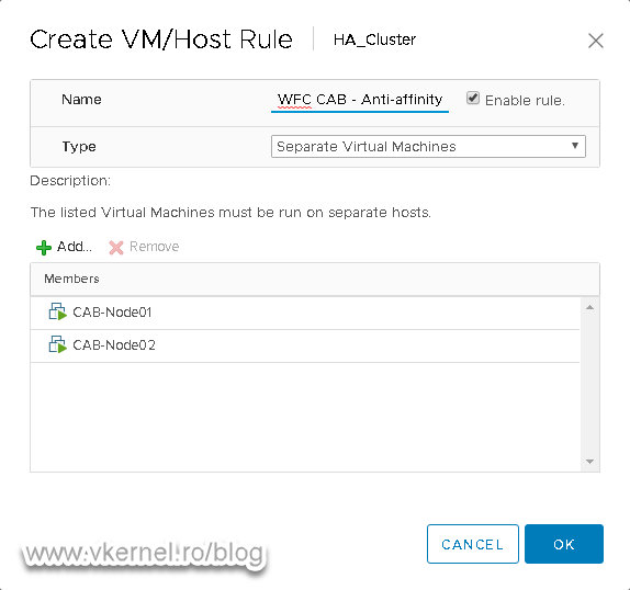
Once you click OK, you should have an anti-affinity rule created in the vCenter console similar to the one bellow.

The last thing that needs to be done is to enforce this anti-affinity rule to strictly apply.
Select your VMware cluster again and go to Configure > Services > vSphere DRS. From the Actions pane click the Edit button.
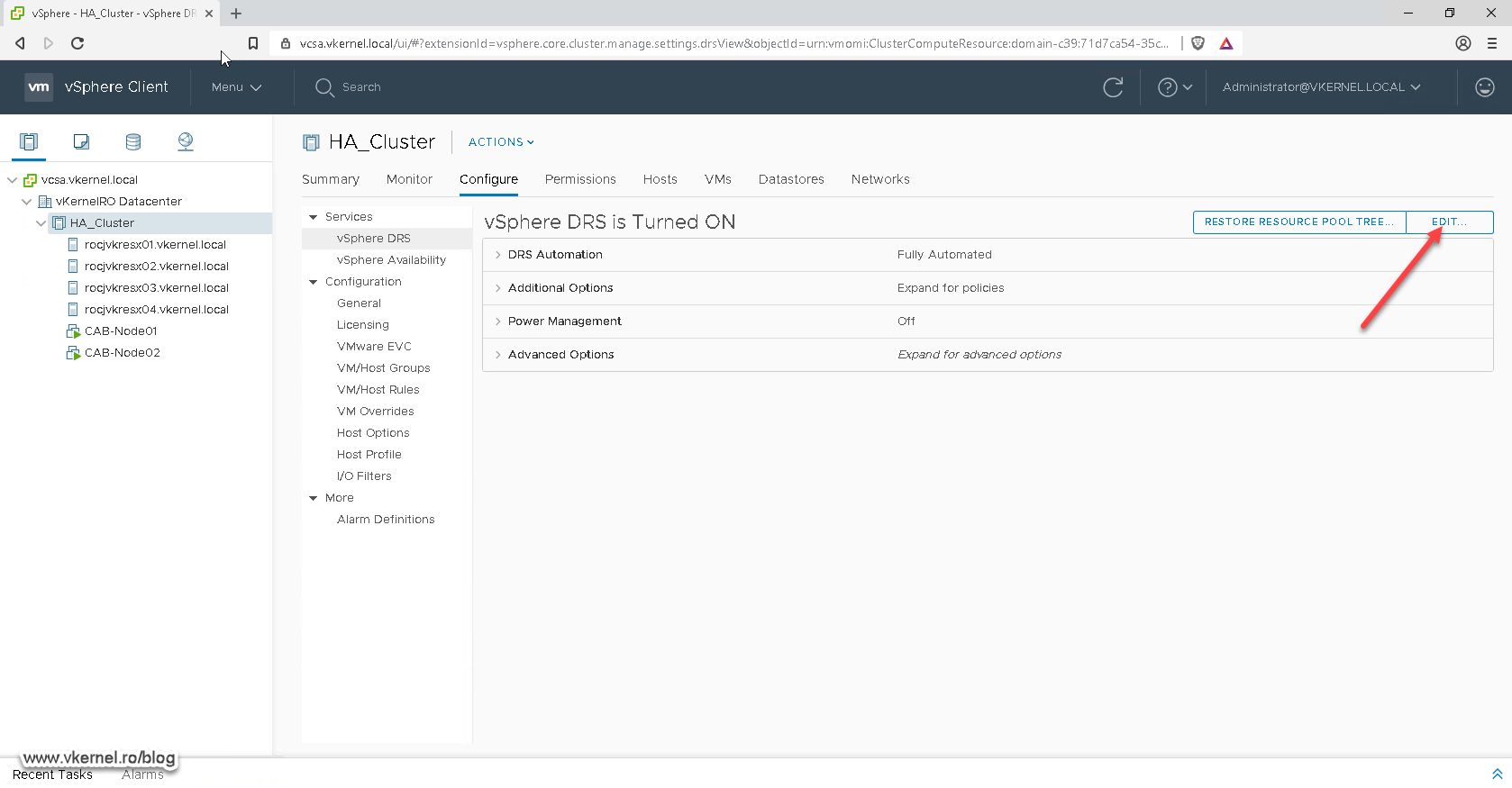
In the window that pops-up hit Add.
Type ForceAffinePoweron in the Options column and give it a value of 1. Click OK to save the changes.
2.4 Testing the Windows Cluster
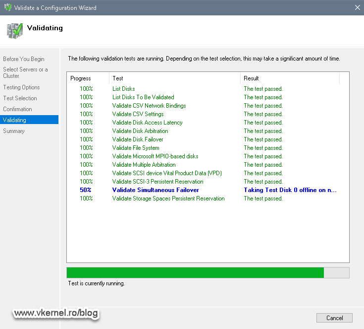
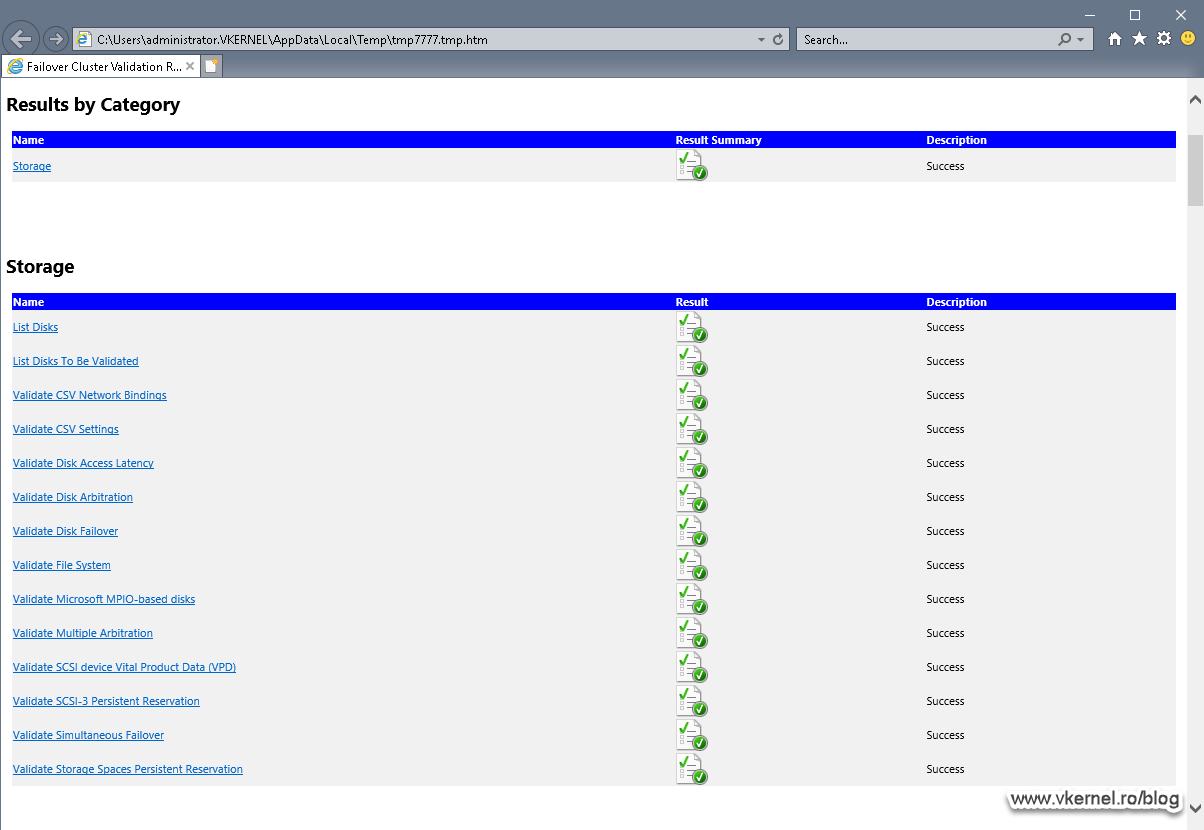
Now when we go and build the Windows Failover Cluster, the storage checks should pass with no problems during the validation wizard, which is exactly what we wanted. If you get any errors or warnings, please post them in the comments area so the community can know about them.
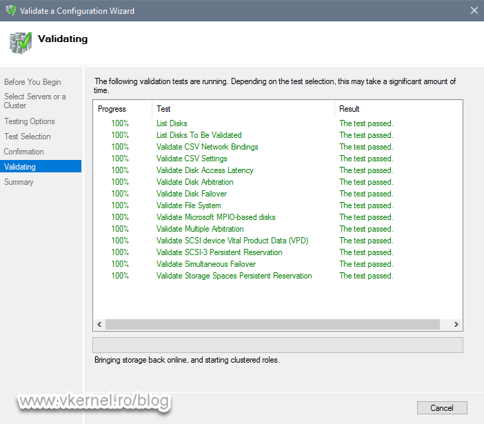
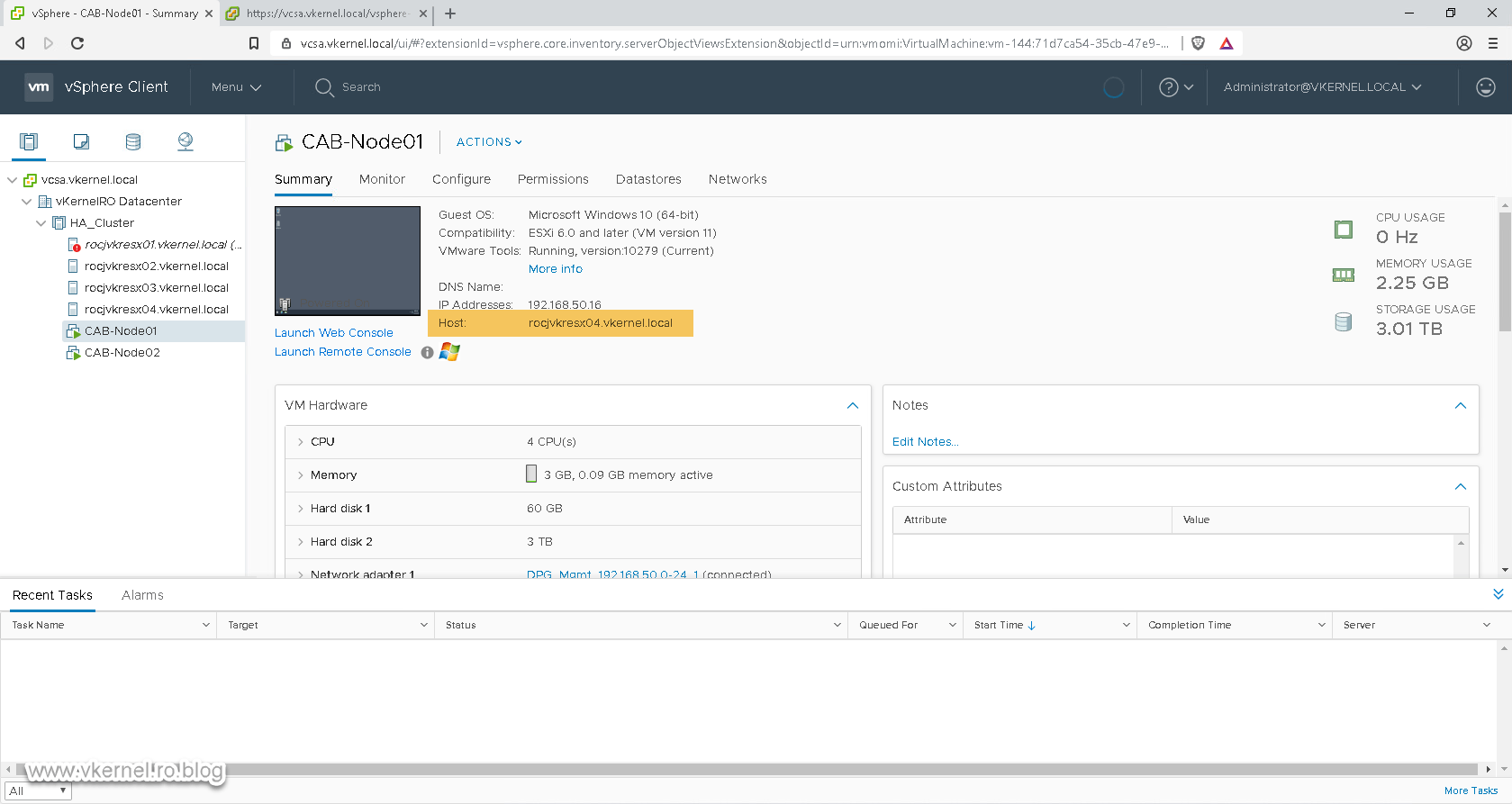
If we want to migrate the VMs to a different ESXi host, no problem, we can do that, and vMotion is doing the job just fine. The validation succeeds,

and transferring the data to a different ESXi host completes with no errors whatsoever.
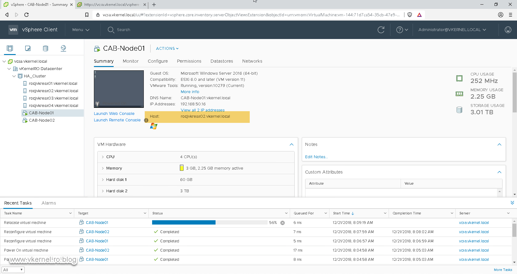
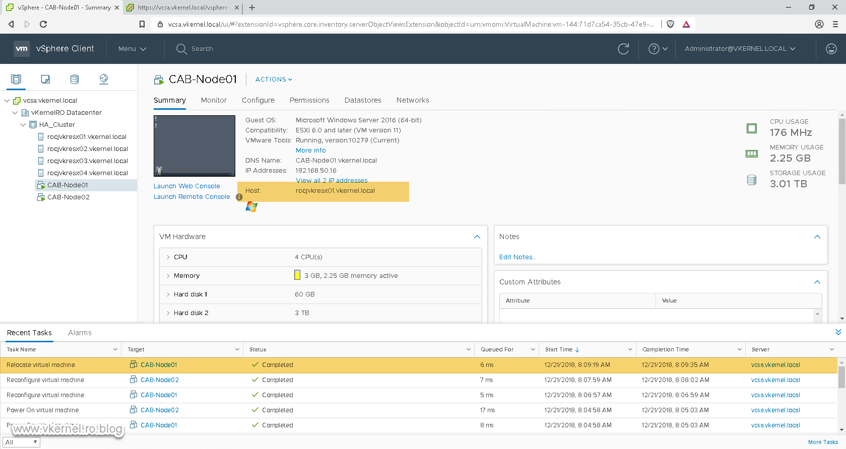
Also, if one the ESXi hosts fails, HA will start the Windows VM on a different host. But remember, we have an anti-affinity rule, so the VM will not be started on an ESXi server where other Windows machines that participate in the Windows Failover Cluster are running.
3. Physical to Virtual
This last type of cluster configuration is pretty much the same as Cluster Across Boxes (CAB), just that now we have at least one Windows physical host involved.
I will not go too deep into the subject here since most of the settings and configurations were covered in the previous section, the CAB section, so if you need extra information, please read that section.
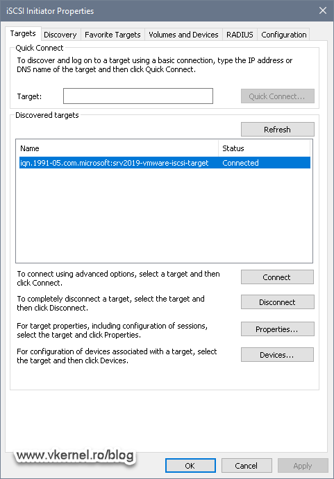
The most important thing in making this work is to map the same LUNs to the physical and virtual machines. It doesn’t really matter if the physical host is connected to the storage device by Fiber Channel or iSCSI as long as the disks/LUNs are mapped to the server.
Here, on the physical box I have connected to my storage array using iSCSI
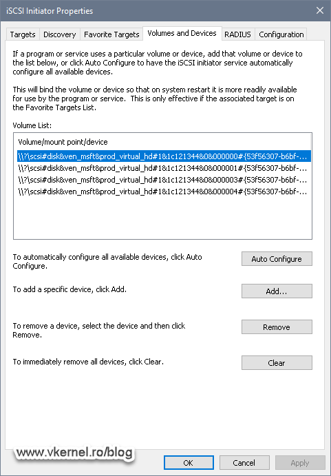
then on the virtual machine, the same LUNs are mapped so both servers can see them.
During the Windows Failover Cluster validation configuration wizard, everything should be good and green.
Off course, the VM running on the VMware infrastructure can be migrated using vMotion but it also benefits of HA, so if an ESXi server goes down, the VM will be restarted on a different one.

Summary
In the end, I will leave it up to you to choose which type of Windows clusters you want to build on your VMware infrastructure, but take advantage of this for your sensitive applications and services so you have at little as possible of downtime. As you just saw, building them it’s a piece-of-cake since no extra hardware and complicated configurations are needed, like in “the real world”.
Want content like this delivered right to your
email inbox?
More similar articles
 Upgrading from VCSA 5.x to VCSA 6.0 with an Embedded Platform Service Controller (PSC)
- Deploying the VMware vCenter 6.0 Appliance (VCSA) with an Embedded Platform Service Controller (PSC)
- Adding a Raw Device Mapping (RDM) to a Virtual Machine
- Deploying and Configuring VMware vCenter Server Appliance 5.x
- Configure Syslog on ESXi 5.x Hosts
- Configuring VMware High Availability (VMHA)
“gives us the best of both worlds”
error – the worst, i highly disrecommend using such a structure because of lower reliability, compability and scalability.
Of course this is just anon internet guy advice, you always choose yourself what to fu…fun with in production.
Thanks a lot for your document Adrian.
I’ve lost 2 hours trying to add a shared disk to the virtual machines getting “Incompatible device backing specified for device ‘0’.” again and again.
So again, thanks a lot. Very complete document
You are welcome
Hi Adrian, Oleg Ulyanov from VMware here.
Thanks a lot for creating this blog with a lot of good information.
Would you mind to make two changes to the content:
1. Remove references to multi-writer flag – this configuration is unsupported and would not be accepted by VMware for WSFC in CaB configuration. You can use the wording from here: https://blogs.vmware.com/apps/2019/05/wsfc-on-vsphere.html or https://docs.vmware.com/en/VMware-vSphere/7.0/vsphere-esxi-vcenter-server-70-setup-wsfc.pdf, p11.
2. Add a mention that starting with vSphere 7.0 VMware supports WSFC in CaB with a clustered VMDK on VMFS: https://docs.vmware.com/en/VMware-vSphere/7.0/com.vmware.vsphere.wsfc.doc/GUID-97B054E2-2EB0-4E10-855B-521A38776F39.html
Let me know if any questions,
Oleg Ulyanov.
Hi Oleg,
Thanks for the heads-up, changes/updates were made to the article.
This is an interesting article. Would it be possible to adapt this type of clustering for printing?
Hi,
Sure, it works. The cluster service does not know if it is a virtual environment or not.
Try it, let me know how it works.
Hey, great article/blog. Would any of the steps change if my nodes are Server 2016? You began with 2003 and 2008 OS. Also, a previous comment mentioned writing about adding the disks within Windows. Did you do that? Would be helpful as you said. Thank you again!
Hi,
It will work great for Server 2016, as for the other article I did not get a chance yet, but it on my table.
Thanks for passing by
Excellent article! Very helpful. Thank you very much!
You are more than welcome.
Thanks for such a detailed article!
Question: can you tell how dangerous it is to use shared VMDKs in a “cluster across boxes”, in the unsupported fashion?
I understand that SCSI-3 Persistent Reservations can’t work this way, but is it critical? Given that WSFC anyway cares to make the shared disk usable on one node only?
Depends on how critical are the VMs/services running on that cluster. You can give it a try with some pilot users and see how it works, but on some heavy clusters I will not try this.
HI can you show how to add these to cluster disks or the windows part of the process
Hi,
Thanks for the idea. I will start creating an article about this, just make sure you are subscribed to my newsletter to be notified when is published.
Hi,
Are you able to provide the information you found from VMware regarding the compliance of this in a production environment?
I’m not able to find any documents telling that this is compatible with WSFC, but i would like to use it 🙂
Hi Robin,
here you go https://docs.vmware.com/en/VMware-vSphere/6.5/vsphere-esxi-vcenter-server-651-setup-mscs.pdf
Hello
I think that the option to share in Multi-writer mode is not compatible with WSFC or MSCS. At least the official vmware documentation does not say that it has to be established.
I’m wrong?
Hi John,
I followed the VMware docs just to be sure and it is supported. I also tested it and it works great.
Let me know if you have any other doubts and I will try to explain them.
Which doc? I’m looking at this one and they explicitly call out the multi-writer option: https://blogs.vmware.com/apps/2019/05/wsfc-on-vsphere.html
Here you go, page 33
https://docs.vmware.com/en/VMware-vSphere/6.7/vsphere-esxi-vcenter-server-67-setup-mscs.pdf
Wrong link? ctrl-F “writer” turns up nothing in that pdf.
Hi Richard,
Link works, try again and clear your browser cache.
https://docs.vmware.com/en/VMware-vSphere/6.7/vsphere-esxi-vcenter-server-67-setup-mscs.pdf